01过流策略实现VLAN间三层隔离
1.1 组网需求
如图 1 所示,为了通信的安全性,某公司将访客、员工、服务器分别划分到VLAN10、VLAN20、VLAN30中。公司希望:
员工、服务器主机、访客均能访问Internet。
访客只能访问Internet,不能与其他任何VLAN的用户通信。
员工A可以访问服务器区的所有资源,但其他员工只能访问服务器A的21端口(FTP服务)。
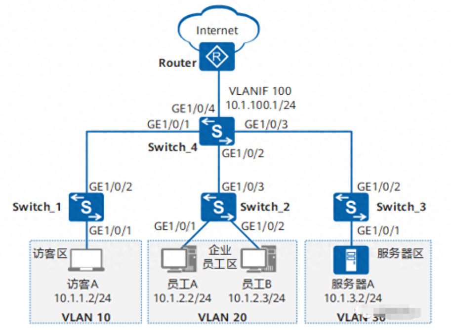
图 1 配置通过流策略实现VLAN间三层隔离组网图
1.2 配置思路
可采用如下思路配置通过流策略实现VLAN间互访控制:
配置VLAN并将各接口加入VLAN,使员工、服务器、访客间二层隔离。
配置VLANIF接口及其IP地址,使员工、服务器、访客间可三层互通。
配置上行路由,使员工、服务器、访客均可通过Switch访问Internet。
配置并应用流策略,使员工A可以访问服务器区的所有资源,其他员工只能访问服务器A的21端口,且只允许员工访问服务器;使访客只能访问Internet。
1.3 操作步骤
【1】配置VLAN并将各接口加入VLAN,使员工、服务器、访客间二层隔离
# 在Switch_1上创建VLAN10,并将接口GE1/0/1以Untagged方式加入VLAN10,接口GE1/0/2以Tagged方式加入VLAN10。Switch_2和Switch_3的配置与Switch_1类似,不再赘述。(详看文章后面的配置文件)
# 在Switch_4上创建VLAN10、VLAN20、VLAN30、VLAN100,并配置接口GE1/0/1~GE1/0/4分别以Tagged方式加入VLAN10、VLAN20、VLAN30、VLAN100。 【2】配置VLANIF接口及其IP地址,使员工、服务器、访客间可以三层互通 # 在Switch_4上创建VLANIF10、VLANIF20、VLANIF30、VLANIF100,并分别配置其IP地址为10.1.1.1/24、10.1.2.1/24、10.1.3.1/24、10.1.100.1/24。 [Switch_4]interfacevlanif10[Switch_4-Vlanif10]ipaddress10.1.1.124[Switch_4-Vlanif10]quit[Switch_4]interfacevlanif20[Switch_4-Vlanif20]ipaddress10.1.2.124[Switch_4-Vlanif20]quit[Switch_4]interfacevlanif30[Switch_4-Vlanif30]ipaddress10.1.3.124[Switch_4-Vlanif30]quit[Switch_4]interfacevlanif100[Switch_4-Vlanif100]ipaddress10.1.100.124[Switch_4-Vlanif100]quit 【3】配置上行路由,使员工、服务器、访客均可通过Switch访问Internet。 # 在Switch_4上配置OSPF基本功能,发布用户网段以及Switch_4与Router之间的互联网段。 [Switch_4]ospf[Switch_4-ospf-1]area0[Switch_4-ospf-1-area-0.0.0.0]network10.1.1.00.0.0.255[Switch_4-ospf-1-area-0.0.0.0]network10.1.2.00.0.0.255[Switch_4-ospf-1-area-0.0.0.0]network10.1.3.00.0.0.255[Switch_4-ospf-1-area-0.0.0.0]network10.1.100.00.0.0.255[Switch_4-ospf-1-area-0.0.0.0]quit[Switch_4-ospf-1]quit Router上需要进行如下配置: 将连接Switch的接口以Tagged方式加入VLAN100,并指定VLANIF100的IP地址与10.1.100.1在同一网段。 配置OSPF基本功能,并发布Switch与Router之间的互联网段。 【4】配置并应用流策略,控制员工、访客、服务器之间的访问 A、通过ACL定义每个流 # 在Switch_4上配置ACL 3000,禁止访客访问员工区和服务器区。 [Switch_4]acl3000[Switch_4-acl-adv-3000]ruledenyipdestination10.1.2.10.0.0.255[Switch_4-acl-adv-3000]ruledenyipdestination10.1.3.10.0.0.255[Switch_4-acl-adv-3000]quit # 在Switch_4上配置ACL 3001,使员工A可以访问服务器区的所有资源,其他员工只能访问服务器A的21端口。 [Switch_4]acl3001[Switch_4-acl-adv-3001]rulepermitipsource10.1.2.20destination10.1.3.10.0.0.255[Switch_4-acl-adv-3001]rulepermittcpdestination10.1.3.20destination-porteq21[Switch_4-acl-adv-3001]ruledenyipdestination10.1.3.10.0.0.255[Switch_4-acl-adv-3001]quit B、配置流分类,区分不同的流 # 在Switch_4上创建流分类c_custom、c_staff,并分别配置匹配规则3000、3001。 [Switch_4]trafficclassifierc_custom
[Switch_4-classifier-c_custom]if-matchacl3000[Switch_4-classifier-c_custom]quit
[Switch_4]trafficclassifierc_staff
[Switch_4-classifier-c_staff]if-matchacl3001[Switch_4-classifier-c_staff]quit C、配置流行为,指定流动作 # 在Switch_4上创建流行为b1,并配置允许动作。 [Switch_4]trafficbehaviorb1
[Switch_4-behavior-b1]permit
[Switch_4-behavior-b1]quit D、配置流策略,关联流分类和流行为 # 在Switch_4上创建流策略p_custom、p_staff,并分别将流分类c_custom、c_staff与流行为b1关联。 [Switch_4]trafficpolicyp_custom
[Switch_4-trafficpolicy-p_custom]classifierc_custombehaviorb1
[Switch_4-trafficpolicy-p_custom]quit
[Switch_4]trafficpolicyp_staff
[Switch_4-trafficpolicy-p_staff]classifierc_staffbehaviorb1
[Switch_4-trafficpolicy-p_staff]quit E、应用流策略,实现员工、访客、服务器之间的访问控制 # 在Switch_4上,分别在VLAN10、VLAN20的入方向应用流策略p_custom、p_staff。 [Switch_4]vlan10[Switch_4-vlan10]traffic-policyp_custominbound
[Switch_4-vlan10]quit
[Switch_4]vlan20[Switch_4-vlan20]traffic-policyp_staffinbound
[Switch_4-vlan20]quit 【5】验证配置结果 配置访客A的IP地址为10.1.1.2/24,缺省网关为VLANIF10接口的IP地址10.1.1.1;配置员工A的IP地址为10.1.2.2/24,缺省网关为VLANIF20接口的从IP地址10.1.2.1;配置员工B的IP地址为10.1.2.3/24,缺省网关为VLANIF20接口的从IP地址10.1.2.1;配置服务器A的IP地址为10.1.3.2/24,缺省网关为VLANIF30接口的从IP地址10.1.3.1。 配置完成后: 访客A不能Ping通员工A、服务器A;员工A和服务器A不能Ping通访客A。 员工A可以Ping通服务器A,即可以使用服务器A的FTP服务,也可以使用服务器A的。 员工B可以Ping不通服务器A,只能使用服务器A的FTP服务。 访客、员工A、员工B、服务器A均可以Ping通Router连接Switch_4的接口的IP地址10.1.100.2/24,也就都可以访问Internet。 1.4 配置文件 Switch_1的配置文件 #sysnameSwitch_1#vlanbatch10#interfaceGigabitEthernet1/0/1
portlink-typeaccess
portdefaultvlan10#interfaceGigabitEthernet1/0/2
portlink-typetrunk
porttrunkallow-passvlan10#return Switch_2的配置文件 #sysnameSwitch_2#vlanbatch20#interfaceGigabitEthernet1/0/1
portlink-typeaccess
portdefaultvlan20#interfaceGigabitEthernet1/0/2
portlink-typeaccess
portdefaultvlan20#interfaceGigabitEthernet1/0/3
portlink-typetrunk
porttrunkallow-passvlan20#return Switch_3的配置文件 #sysnameSwitch_3#vlanbatch30#interfaceGigabitEthernet1/0/1
portlink-typeaccess
portdefaultvlan30#interfaceGigabitEthernet1/0/2
portlink-typetrunk
porttrunkallow-passvlan30#return Switch_4的配置文件 #sysnameSwitch_4#vlanbatch102030100#aclnumber3000
rule5denyipdestination10.1.2.00.0.0.255
rule10denyipdestination10.1.3.00.0.0.255aclnumber3001
rule5permittcpdestination10.1.3.20destination-porteqftp
rule10permitipsource10.1.2.20destination10.1.3.00.0.0.255
rule15denyipdestination10.1.3.00.0.0.255#trafficclassifierc_customoperatororprecedence5
if-matchacl3000trafficclassifierc_staffoperatororprecedence10
if-matchacl3001#trafficbehaviorb1
permit#trafficpolicyp_custommatch-orderconfig
classifierc_custombehaviorb1trafficpolicyp_staffmatch-orderconfig
classifierc_staffbehaviorb1#vlan10
traffic-policyp_custominboundvlan20
traffic-policyp_staffinbound#interfaceVlanif10
ipaddress10.1.1.1255.255.255.0#interfaceVlanif20
ipaddress10.1.2.1255.255.255.0#interfaceVlanif30
ipaddress10.1.3.1255.255.255.0#interfaceVlanif100
ipaddress10.1.100.1255.255.255.0#interfaceGigabitEthernet1/0/1
portlink-typetrunk
porttrunkallow-passvlan10#interfaceGigabitEthernet1/0/2
portlink-typetrunk
porttrunkallow-passvlan20#interfaceGigabitEthernet1/0/3
portlink-typetrunk
porttrunkallow-passvlan30#interfaceGigabitEthernet1/0/4
portlink-typetrunk
porttrunkallow-passvlan100#ospf1
area0.0.0.0
network10.1.1.00.0.0.255
network10.1.2.00.0.0.255
network10.1.3.00.0.0.255
network10.1.100.00.0.0.255#return
 扫一扫咨询微信客服