以太网全双工协议易于在FPGA中实现。 这里的目标是将FPGA连接到10BASE-T连接。
在这里,我们演示了如何将以太网流量直接从FPGA发送到PC。
对于此食谱,您需要:FPGA 开发板,具有 2 个空闲 IO 和一个 20MHz 时钟。
一台带有以太网卡并安装了 TCP-IP 堆栈的 PC(如果你能浏览 Internet,你就很好)。
(可选)网络集线器或交换机。
以下是使用以太网集线器或交换机的典型测试设置视图。
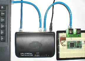
使用集线器或交换机可让电脑在执行此实验时保持与常规网络(如果有)的连接。 但您也可以将FPGA直接连接到PC。我们在这里使用带有外部 20MHz 振荡器的Pluto板。
将FPGA板上的两个IO连接到以太网电缆。
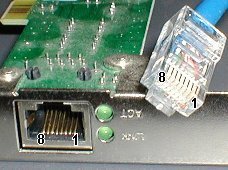
如果电缆的另一端连接到集线器或交换机(如上图所示),请使用以太网电缆的引脚 1 和 2。
如果电缆的另一端直接连接到 PC,请使用引脚 3 和 6。
有关引脚编号,请从这张图片中获取帮助:
请注意,极性通常无关紧要,因为信号是差分的,以太网设备可以从输入信号中检测极性。此外,即使这在实践中有效,我们也无法通过仅将FPGA连接到电缆(我们需要滤波器和变压器)来满足以太网电气要求。 因此,让我们将其视为“实验室”实验。
在命令行中键入“ipconfig /all”。
写下您的“物理地址”和“IP 地址”。
编译以下 Verilog HDL 代码。
确保:
更新代码中的数据值(“IP 源”、“IP 目标”和“物理地址”)。
为您的电路板分配正确的引脚(只使用了 3 个引脚!
| moduleTENBASET_TxD(clk20, Ethernet_TDp, Ethernet_TDm);// a 20MHz clock (this code won't work with a different frequency)inputclk20;// the two differential 10BASE-T outputsoutputEthernet_TDp, Ethernet_TDm;// "IP source" - put an unused IP - if unsure, see comment below after the source codeparameterIPsource_1 = 192;parameterIPsource_2 = 168;parameterIPsource_3 = 0;parameterIPsource_4 = 44;// "IP destination" - put the IP of the PC you want to send toparameterIPdestination_1 = 192;parameterIPdestination_2 = 168;parameterIPdestination_3 = 0;parameterIPdestination_4 = 2;// "Physical Address" - put the address of the PC you want to send toparameterPhysicalAddress_1 = 8'h00;parameterPhysicalAddress_2 = 8'h07;parameterPhysicalAddress_3 = 8'h95;parameterPhysicalAddress_4 = 8'h0B;parameterPhysicalAddress_5 = 8'hFB;parameterPhysicalAddress_6 = 8'hAF;//////////////////////////////////////////////////////////////////////// sends a packet roughly every secondreg[23:0] counter;always@(posedgeclk20) counter<=counter+1;regStartSending;always@(posedgeclk20) StartSending<=&counter;//////////////////////////////////////////////////////////////////////// we send a UDP packet, 18 bytes payload// calculate the IP checksum, big-endian styleparameterIPchecksum1 = 32'h0000C53F + (IPsource_1<<8)+IPsource_2+(IPsource_3<<8)+IPsource_4+ (IPdestination_1<<8)+IPdestination_2+(IPdestination_3<<8)+(IPdestination_4);parameterIPchecksum2 = ((IPchecksum1&32'h0000FFFF)+(IPchecksum1>>16));parameterIPchecksum3 =~((IPchecksum2&32'h0000FFFF)+(IPchecksum2>>16));reg[6:0] rdaddress;reg[7:0] pkt_data;always@(posedgeclk20)case(rdaddress)// Ethernet preamble 7'h00: pkt_data <= 8'h55; 7'h01: pkt_data <= 8'h55; 7'h02: pkt_data <= 8'h55; 7'h03: pkt_data <= 8'h55; 7'h04: pkt_data <= 8'h55; 7'h05: pkt_data <= 8'h55; 7'h06: pkt_data <= 8'h55; 7'h07: pkt_data <= 8'hD5;// Ethernet header 7'h08: pkt_data <= PhysicalAddress_1; 7'h09: pkt_data <= PhysicalAddress_2; 7'h0A: pkt_data <= PhysicalAddress_3; 7'h0B: pkt_data <= PhysicalAddress_4; 7'h0C: pkt_data <= PhysicalAddress_5; 7'h0D: pkt_data <= PhysicalAddress_6; 7'h0E: pkt_data <= 8'h00; 7'h0F: pkt_data <= 8'h12; 7'h10: pkt_data <= 8'h34; 7'h11: pkt_data <= 8'h56; 7'h12: pkt_data <= 8'h78; 7'h13: pkt_data <= 8'h90;// IP header 7'h14: pkt_data <= 8'h08; 7'h15: pkt_data <= 8'h00; 7'h16: pkt_data <= 8'h45; 7'h17: pkt_data <= 8'h00; 7'h18: pkt_data <= 8'h00; 7'h19: pkt_data <= 8'h2E; 7'h1A: pkt_data <= 8'h00; 7'h1B: pkt_data <= 8'h00; 7'h1C: pkt_data <= 8'h00; 7'h1D: pkt_data <= 8'h00; 7'h1E: pkt_data <= 8'h80; 7'h1F: pkt_data <= 8'h11; 7'h20: pkt_data <= IPchecksum3[15:8]; 7'h21: pkt_data <= IPchecksum3[ 7:0]; 7'h22: pkt_data <= IPsource_1; 7'h23: pkt_data <= IPsource_2; 7'h24: pkt_data <= IPsource_3; 7'h25: pkt_data <= IPsource_4; 7'h26: pkt_data <= IPdestination_1; 7'h27: pkt_data <= IPdestination_2; 7'h28: pkt_data <= IPdestination_3; 7'h29: pkt_data <= IPdestination_4;// UDP header 7'h2A: pkt_data <= 8'h04; 7'h2B: pkt_data <= 8'h00; 7'h2C: pkt_data <= 8'h04; 7'h2D: pkt_data <= 8'h00; 7'h2E: pkt_data <= 8'h00; 7'h2F: pkt_data <= 8'h1A; 7'h30: pkt_data <= 8'h00; 7'h31: pkt_data <= 8'h00;// payload 7'h32: pkt_data <= 8'h00; // put here the data that you want to send 7'h33: pkt_data <= 8'h01; // put here the data that you want to send 7'h34: pkt_data <= 8'h02; // put here the data that you want to send 7'h35: pkt_data <= 8'h03; // put here the data that you want to send 7'h36: pkt_data <= 8'h04; // put here the data that you want to send 7'h37: pkt_data <= 8'h05; // put here the data that you want to send 7'h38: pkt_data <= 8'h06; // put here the data that you want to send 7'h39: pkt_data <= 8'h07; // put here the data that you want to send 7'h3A: pkt_data <= 8'h08; // put here the data that you want to send 7'h3B: pkt_data <= 8'h09; // put here the data that you want to send 7'h3C: pkt_data <= 8'h0A; // put here the data that you want to send 7'h3D: pkt_data <= 8'h0B; // put here the data that you want to send 7'h3E: pkt_data <= 8'h0C; // put here the data that you want to send 7'h3F: pkt_data <= 8'h0D; // put here the data that you want to send 7'h40: pkt_data <= 8'h0E; // put here the data that you want to send 7'h41: pkt_data <= 8'h0F; // put here the data that you want to send 7'h42: pkt_data <= 8'h10; // put here the data that you want to send 7'h43: pkt_data <= 8'h11; // put here the data that you want to send default: pkt_data <= 8'h00;endcase//////////////////////////////////////////////////////////////////////// and finally the 10BASE-T's magicreg[3:0] ShiftCount;regSendingPacket;always@(posedgeclk20)if(StartSending) SendingPacket<=1;elseif(ShiftCount==14 && rdaddress==7'h48) SendingPacket<=0;always@(posedgeclk20) ShiftCount <= SendingPacket ? ShiftCount+1 : 15;wirereadram = (ShiftCount==15);always@(posedgeclk20)if(ShiftCount==15) rdaddress <= SendingPacket ? rdaddress+1 : 0;reg[7:0] ShiftData;always@(posedgeclk20)if(ShiftCount[0]) ShiftData <= readram ? pkt_data : {1'b0, ShiftData[7:1]};// generate the CRC32reg[31:0] CRC;regCRCflush;always@(posedgeclk20)if(CRCflush) CRCflush <= SendingPacket;elseif(readram) CRCflush <= (rdaddress==7'h44);regCRCinit;always@(posedgeclk20)if(readram) CRCinit <= (rdaddress==7);wireCRCinput = CRCflush ? 0 : (ShiftData[0] ^ CRC[31]);always@(posedgeclk20)if(ShiftCount[0]) CRC <= CRCinit ? ~0 : ({CRC[30:0],1'b0} ^ ({32{CRCinput}} & 32'h04C11DB7));// generate the NLPreg[17:0] LinkPulseCount;always@(posedgeclk20) LinkPulseCount <= SendingPacket ? 0 : LinkPulseCount+1;regLinkPulse;always@(posedgeclk20) LinkPulse <= &LinkPulseCount[17:1];// TP_IDL, shift-register and manchester encoderregSendingPacketData;always@(posedgeclk20) SendingPacketData <= SendingPacket;reg[2:0] idlecount;always@(posedgeclk20)if(SendingPacketData) idlecount<=0;elseif(~&idlecount) idlecount<=idlecount+1;wiredataout = CRCflush ? ~CRC[31] : ShiftData[0];regqo;always@(posedgeclk20) qo <= SendingPacketData ? ~dataout^ShiftCount[0] : 1;regqoe;always@(posedgeclk20) qoe <= SendingPacketData | LinkPulse | (idlecount<6);regEthernet_TDp;always@(posedgeclk20) Ethernet_TDp <= (qoe ? qo : 1'b0);regEthernet_TDm;always@(posedgeclk20) Ethernet_TDm <= (qoe ? ~qo : 1'b0);endmodule |
About the "IP source" that you have to choose in the code above, pick something that is compatible with your network, but still unused.The example network shown above have IPs starting with "192.168.0" (the PC IP is 192.168.0.2 with a mask of 255.255.255.0). So here IPs like 192.168.0.x can be used. To check if an IP is used or not, "ping" it.
在 PC 上运行此UDP 接收器软件(包括源代码)。
你会得到这样的东西:
上面的代码在每个 UDP 数据包中发送 18 个数据字节。 这 18 个字节可以来自任何地方,因此,例如,您可以修改代码以发送 FPGA 引脚的值。
玩得开心发送UDP数据包!
 在 8 个引脚中,只使用了 4 个:
TD+(传输+)
TD-(传输-)
RD+(接收+)
RD-(接收-)
在发射之前,每个电台都必须监听以确保线路是空闲的(“载波检测”)。
尽管如此,两个电台仍有可能同时传输。 因此,必须存在一个复杂的协议来中止(“冲突检测”)并在以后恢复传输。
您可以获得两倍的带宽。
每个站点都有一个专用的介质,可以随时开始传输,而不会出现并发症(CSMA/CD 不再适用)。
集线器是一种简单的电子设备,它在每个链路之间提供电气隔离,但仍然将它们“逻辑”地连接在一起。 这迫使通信是半双工的。 更糟糕的是:在任何给定时间,只有一台计算机可以说话。 因此,网络带宽在所有计算机之间共享。
交换机(或“交换机集线器”)是一种更复杂的电子设备,它在电气和逻辑上隔离每个计算机链路。 它通过在重新传输之前在内部存储每个传输的数据来做到这一点。 因此,每台计算机都可以随时说话:这允许全双工通信。 更好的是:每台计算机都具有完整的链路带宽。 而且由于介质不共享,因此每个站点仅接收发给自己的数据包(隐私性得到改善)。
集线器:每个链路上的半双工,所有计算机之间共享 10Mbps。慢。。。
交换:每个链路上的全双工,每台计算机专用 20Mbps(单向 10Mbps)。快!
UDP 部分包含要发送的数据(“有效负载”)。
IP 部分允许数据包通过 Internet 路由。
以太网部分允许数据包在以太网上本地发送。
以太网前导码/SFD(同步器):55 55 55 55 55 55 D55
以太网目标地址:00 10 A4 7B EA 80
以太网源地址:00 12 34 56 78 90
以太网类型: 08 00 (=IP)
IP 标头:45 00 00 2E B3 FE 00 00 80
IP 协议:11 (=UDP)
IP 校验和: 05 40
IP 源 (192.168.0.44): C0 A8 00 2C
IP 目标 (192.168.0.4): C0 A8 00 04
UPD 源端口 (1024):04 00
UPD 目标端口 (1024):04 00
UDP 有效载荷长度 (18): 00 1A
UPD 校验和: 2D E8
UDP 有效负载(18 字节):00 01 02 03 04 05 06 07 08 09 0A 0B 0C 0D 0E 0F 10 11
以太网校验和: B3 31 88 1B
 每次按下“发送”按钮时,软件都会构建一个数据包,显示它并将其发送到串行端口(这将在本项目的第 3 部分后面有用)。
逻辑“0”作为高位发送,后跟低位。
逻辑“1”作为低位发送,后跟高位。
| ram512ram( .data(ram_input), .wraddress(wraddress), .clock(clk), .q(ram_output), .rdaddress(rdaddress)); |
| wireStartSending; // pulse indicating when to start sending the packetregSendingPacket;always@(posedgeclk)if(StartSending) SendingPacket<=1;elseif(DoneSending) SendingPacket<=0; |
| reg[3:0] ShiftCount; // count from 0 to 15, as 16 clocks are required per 8-bits bytesalways@(posedgeclk) if(SendingPacket) ShiftCount <= ShiftCount+1; else ShiftCount <= 0; |
| wirereadram = (ShiftCount==15); // time to read a new byte from the RAM?reg[7:0] ShiftData;always@(posedgeclk)if(ShiftCount[0]) ShiftData <= readram ? ram_output : {1'b0, ShiftData[7:1]};always@(posedgeclk)if(readram) rdaddress <= SendingPacket ? rdaddress+1 : 0; |
| reg[2:0] idlecount; // enough bits to count 3 bit-times always@(posedgeclk)if(SendingPacket) idlecount<=0; elseif(~&idlecount) idlecount<=idlecount+1; |
| regqo;always@(posedgeclk) qo <= SendingPacket ? ~ShiftData[0]^ShiftCount[0] : 1;regqoe;always@(posedgeclk) qoe <= SendingPacket | (idlecount<6);regq1;always@(posedgeclk) q1 <= (qoe ? qo : 1'b0);regq2;always@(posedgeclk) q2 <= (qoe ? ~qo : 1'b0); |
软件侦听端口 1024。 如果它在此端口上收到数据包,则会显示它获得了多少字节。
该软件还可以在端口 1024 上发送。只需按下“发送 UDP”按钮即可。
 您可以向自己发送数据包 - 只需使用您机器自己的 IP。 但在这种情况下,数据包是在内部路由的,永远没有机会进入网络,所以这不太有用。要查找 PC 的 IP 或以太网 MAC 地址,您可以在命令行中键入“ipconfig /all”。请注意,端口值 1024 在软件中是硬编码的(在 GUI 中只能配置目标 IP 和有效负载长度)。 这在实践中不是问题,因为您的计算机不太可能有另一个应用程序已经在侦听此特定端口。
在网络上创建合法端口。
“嗅探”网络(监视数据包) - 只需将接收器并行连接到另一个连接即可。
差分接收器电路(简单)。
时钟提取电路(困难部分)。
前导码同步器、解串器和以太网校验和检查器(在FPGA中轻松完成)。
 第二个晶体管集电极上的2K电阻高于第一个晶体管(1K)上的值,以帮助在输出端获得50%的占空比信号。 否则,输出端的信号不是方形的......关于电容耦合:我相信它与电感耦合一样好用,但有一个缺点: 当您将电缆插入接收器时,接收器和驱动器之间的电压电位差可能会向接收器发送电流脉冲 (如果驱动器没有被变压器隔离)。 只是我的想法,我在任何地方都没有找到任何相关信息。有人有更多信息吗?
逻辑“0”以高电平(50ns)后跟低电平(50ns)(故障沿)的形式发送。
逻辑“1”以低电平(50ns)发送,后跟高电平(50ns)(上升沿)。
使用更快的时钟对编码信号进行过采样,并使用常规FPGA逻辑(边沿检测器和状态机)提取位。
使用带有改进的相位比较器电路的PLL来重新生成发送器使用的时钟。
使用固定延迟不可重新触发的单稳态,其持续时间为 1.5 编码位(75BASE-T 为 10ns)。 单稳态由中间位转换触发,并忽略位间距转换。
对传入的数据进行采样和同步。
检测边缘并启动计数器。诀窍在于,计数器被制作成忽略任何后续边沿,直到它翻转(仅检测曼彻斯特中位转换)。
一旦检测到边沿,下一个位在 3 个计数后可用 (在48MHz时,周期约为21ns,因此三次计数为63ns,就在下一个位的中间)。 我们将每个位移入一个 8 位移位寄存器。
| reg[2:0] in_data;always@(posedgeclk48) in_data <= {in_data[1:0], manchester_data_in};reg[1:0] cnt;always@(posedgeclk48)if(|cnt || (in_data[2] ^ in_data[1])) cnt<=cnt+1;reg[7:0] data;regnew_bit_avail;always@(posedgeclk48) new_bit_avail <= (cnt==3);always@(posedgeclk48)if(cnt==3) data<={in_data[1],data[7:1]}; |
| regend_of_Ethernet_frame;reg[4:0] sync1;always@(posedgeclk48)if(end_of_Ethernet_frame) sync1 <= 0;elseif(new_bit_avail)beginif(!(data==8'h55 || data==8'hAA)) // not preamble? sync1 <= 0;elseif(~&sync1) // if all bits of this "sync1" counter are one, we decide that enough of the preamble // has been received, so stop counting and wait for "sync2" to detect the SFD sync1 <= sync1 + 1; // otherwise keep countingendreg[9:0] sync2;always@(posedgeclk48)if(end_of_Ethernet_frame) sync2 <= 0;elseif(new_bit_avail)beginif(|sync2) // if the SFD has already been detected (Ethernet data is coming in) sync2 <= sync2 + 1; // then count the bits coming inelseif(&sync1 && data==8'hD5) // otherwise, let's wait for the SFD (0xD5) sync2 <= sync2 + 1;endwirenew_byte_available = new_bit_avail && (sync2[2:0]==3'h0) && (sync2[9:3]!=0); |
| reg[2:0] transition_timeout;always@(posedgeclk48)if(in_data[2]^in_data[1]) // transition detected? transition_timeout <= 0;elseif(~&cnt) transition_timeout <= transition_timeout + 1;always@(posedgeclk48) end_of_Ethernet_frame <= &transition_timeout; |
| wire[7:0] q_fifo;fifo myfifo(.data(data), .wrreq(new_byte_available), .wrclk(clk48), .q(q_fifo), .rdreq(rdreq), .rdclk(clk), .rdempty(rdempty));wireTxD_busy;wireTxD_start = ~TxD_busy & ~rdempty;assignrdreq = TxD_start;async_transmitter async_txd(.clk(clk), .TxD(TxD), .TxD_start(TxD_start), .TxD_busy(TxD_busy), .TxD_data(q_fifo)); |
 扫一扫咨询微信客服